
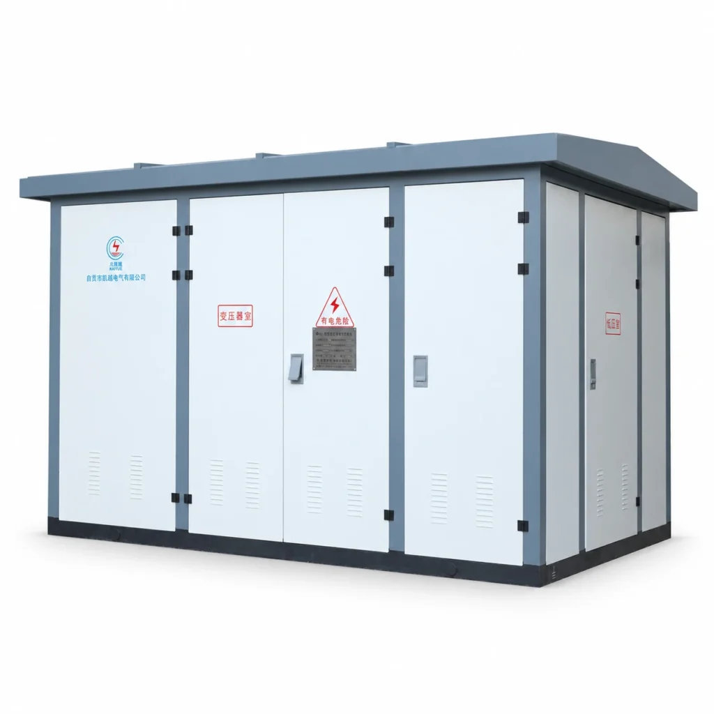
HBW-10 Package Substation is a coordinated arrangement of medium-voltage switching, a transformer and low-voltage distribution. Read the transformer options, load-switch configuration data and service conditions separately, then coordinate them through the project single-line diagram.
HBW-10 Package Substation Specifications
Substation Arrangement
| Parameter | Specification / configuration |
|---|---|
| Documented transformer capacity range | 80–1600 kVA |
| High-voltage options shown in the source | 6 / 6.3 / 10 kV transformer configurations |
| Low-voltage side | 0.4 kV |
| Enclosure | Metal-enclosed outdoor package arrangement |
| Transformer and switchgear selection | Matched to the project electrical scheme |
Transformer Series Data
| Capacity (kVA) | No-load loss (kW) | Load loss (kW) | No-load current (%) |
|---|---|---|---|
| 80 | 0.19 | 1.1 | 1.1 |
| 100 | 0.22 | 1.3 | 1.0 |
| 160 | 0.31 | 1.85 | 0.8 |
| 200 | 0.32 | 2.25 | 0.7 |
| 250 | 0.45 | 2.65 | 0.7 |
| 315 | 0.54 | 3.05 | 0.6 |
| 400 | 0.65 | 3.8 | 0.6 |
| 500 | 0.75 | 4.5 | 0.5 |
| 630 | 0.91 | 5.3 | 0.5 |
| 800 | 1.08 | 6.8 | 0.5 |
| 1000 | 1.26 | 8.1 | 0.4 |
| 1250 | 1.54 | 9.5 | 0.4 |
| 1600 | 1.86 | 11.4 | 0.4 |
Load-Switch Configuration Data
| Parameter | 400 A version | 630 A version |
|---|---|---|
| Rated current | 400 A | 630 A |
| Rated working voltage | 12 kV | 12 kV |
| Impulse withstand voltage | 75 kV; 85 kV across the isolating distance | 75 kV; 85 kV across the isolating distance |
| Power-frequency withstand voltage | 42 kV; 48 kV across the isolating distance | 42 kV; 48 kV across the isolating distance |
| Short-time withstand current / duration | 12.5 kA / 2 s | 16 kA / 4 s |
| Dynamic withstand current | 31.5 kA | 40 kA |
| Short-circuit making current | 31.5 kA | 40 kA |
| Load operating cycles | 100 | 100 |
| Mechanical operating cycles | 2000 | 3000 |
Service Conditions
| Parameter | Specification / configuration |
|---|---|
| Maximum ambient temperature | +45 °C |
| Maximum monthly mean temperature | +20 °C |
| Daily/monthly mean relative humidity | Up to 95% / 90% |
| Altitude | Up to 1000 m |
| Wind pressure | Up to 700 Pa; approximately 35 m/s as stated in the source |
| Horizontal seismic acceleration | Up to 0.3 g |
| Maximum installation inclination | 3° |
Ratings and options apply to the selected configuration. The agreed drawings and equipment schedule define the supplied assembly.
Coordinate the complete substation
The medium-voltage switching, transformer and low-voltage distribution perform different functions and must be coordinated as one electrical arrangement. Transformer capacity, voltage combination, protection, metering and the outgoing load schedule should be defined before selecting the enclosure and equipment layout.
Use the ratings for the selected components
The transformer table lists series values for equipment selection. Final transformer test conditions and guaranteed data are specified in the agreed technical schedule. The load-switch table separates the 400 A and 630 A arrangements. A 12 kV load-switch equipment rating and a 10 kV transformer/network application describe different parts of the substation.
Plan the outdoor installation
Provide the intended site, available footprint, access and cable routes. Ventilation, environmental exposure, earthing and the interfaces with incoming and outgoing cables are reviewed with the chosen electrical scheme. Documents and inspection requirements are agreed for the selected equipment scope.
Information for Selection
- Transformer capacity, high/low voltage and load profile
- Required switch rating, protection and metering scheme
- Low-voltage circuit schedule and cable interfaces
- Outdoor location, footprint, access, inspection and document requirements
Explore the application solutions for your industry and include the project specification with your enquiry.
Related selection and acceptance guides
The 10 kV system versus 12 kV equipment guide explains the different voltage quantities used across a package substation. Use it with the component tables above and the approved single-line diagram.
Define whether the factory acceptance scope covers the complete assembled substation, specific components, or both, and identify the corresponding documents. Compare package substation requirements and consult the residential-area application case for context. Case information does not establish the rating of a new configuration.