
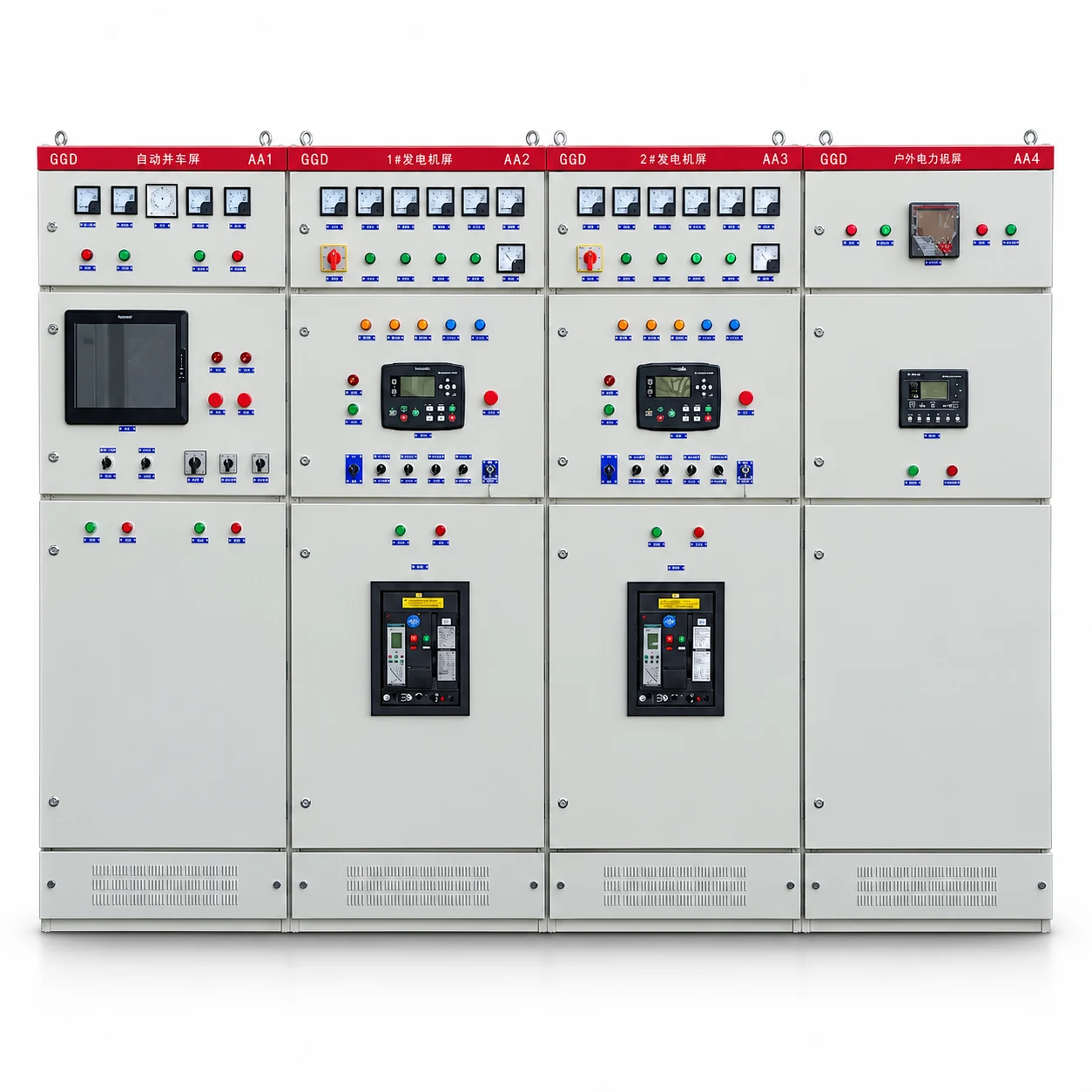
A useful GGD switchgear enquiry starts with the electrical scheme, not a cabinet photo or a series maximum. GGD is a fixed low-voltage distribution assembly. The supplied series information lists GGD1, GGD2 and GGD3 as basic variants with different current and short-time withstand values. A project specification should identify one coherent configuration before a quotation or drawing is accepted.
Use the checklist below to prepare a technical enquiry. It complements the GGD fixed low-voltage switchgear product page, where the model-specific tables and service conditions are listed.
1. Send the network and single-line diagram
State the intended system voltage and frequency, incoming supply arrangement, earthing scheme, and the location of the assembly in the distribution system. The supplied basic-variant data lists 380 V AC and 50 Hz. A project with a different frequency or other special conditions needs a separately confirmed configuration; the model name alone does not establish it.
Mark the incoming circuits, bus couplers, outgoing feeders and any auxiliary supplies on the single-line diagram. If drawings are still preliminary, identify which values are provisional so they are not mistaken for an agreed manufacturing schedule.
2. Separate the GGD basic variants
Specify the selected basic variant and check its values together. The source data lists GGD1 with 400, 600/630 and 1000 A current options and 15 kA short-time withstand for 1 second; GGD2 with 600, 1000 and 1500/1600 A options and 30 kA; and GGD3 with 2000, 2500 and 3150 A options and 50 kA. Peak withstand values are listed separately on the product page.
These are variant entries, not a menu from which the highest value of each column can be combined. Enhanced current or short-circuit arrangements mentioned elsewhere in the series data require a separately defined design and confirmation. Ask for one technical schedule that states the proposed variant, busbar ratings, circuit ratings and corresponding verification records.
3. Provide an outgoing circuit schedule
For each feeder, list its purpose, design current, protective device, control and metering requirements, cable details and any reserve capacity. A main busbar rating does not automatically become every outgoing feeder's rating. The actual distribution arrangement depends on the agreed incoming and outgoing circuit schedule.
If a circuit serves a critical load, describe the intended isolation and continuity strategy in the project documents. A cabinet type alone cannot establish the permitted maintenance procedure or guarantee uninterrupted supply. The fixed versus withdrawable guide explains that construction choice separately.
4. State the fault duty at the installation point
Provide the prospective short-circuit level and the required duration at the proposed assembly location. Compare those values with the selected variant's short-time withstand rating and the specified protective devices. Short-time and peak withstand are different checks; do not exchange their numbers.
If the fault study is pending, make that explicit in the enquiry. A quotation based on an assumed fault level should not be treated as a final technical acceptance.
5. Describe the installation environment
The supplied GGD service conditions are for indoor installation. They include an ambient range of −5 to +40 °C, a 24-hour mean up to +35 °C, and an altitude up to 2000 m for the stated basic conditions. Humidity, vibration, impact and corrosive atmosphere also need review. For a different site condition, request a project-specific assessment instead of silently applying the standard table.
State room dimensions, access clearances, cable entry direction, ventilation constraints and the enclosure protection required by the project. The product data lists IP30 as the standard enclosure protection and other options according to configuration. Protection grade, cable space and maintenance access should be confirmed for the offered assembly, not inferred from a catalogue photograph.
6. Agree the documents and acceptance scope
Before production or final acceptance, identify the required drawing revision, circuit schedule, component list, inspection scope and records. Record open technical items with an owner and a resolution date. The factory acceptance test checklist provides a separate framework for agreeing inspection and document close-out.
For a quotation, the most useful starting package is the single-line diagram, circuit schedule, system voltage and frequency, fault-duty study, room and service conditions, required protection and metering functions, and the destination's applicable project requirements. Use the switchgear enquiry checklist for the wider request, then send the project specification for a configuration-specific review.