
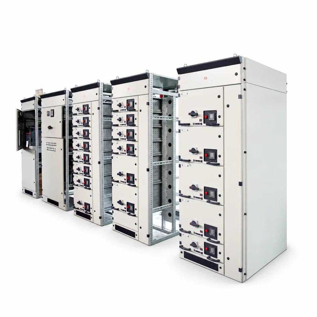
GCK-II Switchgear is a low-voltage withdrawable family for power distribution and motor-control centers. Specify the feeder schedule, unit requirements, busbar data, controls and installation conditions for the selected lineup.
GCK-II Switchgear Specifications
Electrical Selection Data
| Parameter | Source value |
|---|---|
| Operating voltage | 380 / 400 / 660 / 690 V |
| Frequency | 50 / 60 Hz |
| Horizontal busbar current | ≤ 5000 A |
| Vertical busbar current | ≤ 1600 A |
| Unit circuit current | ≤ 630 A |
| Horizontal busbar short-time withstand (1 s) | 100 kA |
| Vertical busbar short-time withstand (1 s) | 65 kA |
| Impulse withstand voltage | 8 kV |
| Degree of protection | IP30; IP40 / IP54 options |
Ratings and options apply to the selected configuration. The agreed drawings and equipment schedule define the supplied assembly.
Distribution and motor-control circuits
Power distribution and motor control place different demands on switching devices, protection and operating frequency. Feeder units are selected from the circuit schedule, while incoming and coupling sections are coordinated with the main supply and short-circuit requirements. Auxiliary supplies, control circuits and interlocks should be identified before the lineup is finalized.
Plan operating and maintenance access
Withdrawable construction provides a distinct functional-unit arrangement, but the final access and isolation procedures depend on the assembled system. Enclosure protection, cable entry, available working space and the service conditions should be reviewed together with the required electrical ratings.
Information for Selection
- Supply voltage, frequency and load schedule
- Main/vertical busbar and outgoing circuit currents
- Fault level and required enclosure protection
- Motor starting, control supply, metering and installation layout
Explore the application solutions for your industry and include the project specification with your enquiry.