
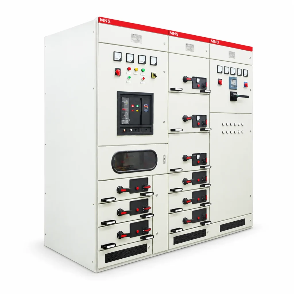
MNS 2.0 Switchgear is a modular low-voltage switchgear and controlgear family for distribution and motor-control duties. Check the horizontal and vertical busbar data independently and confirm the selected construction, circuit ratings and installation conditions.
MNS 2.0 Switchgear Specifications
Electrical Selection Data
| Parameter | Specification / configuration |
|---|---|
| Rated operating voltage | 400 / 690 V AC |
| Rated insulation voltage | 1000 V AC |
| Rated frequency | 50 / 60 Hz, according to configuration |
| Horizontal busbar current options | 1000 / 1600 / 2500 / 3150 / 4000 / 6300 A |
| Horizontal busbar short-time withstand current | 65 / 100 kA for 1 s, according to configuration |
| Vertical busbar short-time withstand current | 30 kA for 1 s for the documented arrangement |
| Power-frequency withstand test | 2500 V for 1 min |
| Enclosure protection | IP30 for the documented arrangement |
Documented Cabinet Dimensions
| Parameter | Specification / configuration |
|---|---|
| Width options | 600 / 800 / 1000 mm |
| Depth options | 800 / 1000 mm |
| Height | 2200 mm |
Ratings and options apply to the selected configuration. The agreed drawings and equipment schedule define the supplied assembly.
Functional units and circuit organization
Incoming, coupling, outgoing and motor-control functions can require different devices and compartment arrangements. The selected design should identify how each functional unit connects to the distribution system and how operating and maintenance access is managed. Circuit ratings must be coordinated with the main and distribution busbars rather than inferred from the overall assembly rating.
Project-specific design review
The electrical schedule determines circuit-breaker selection, motor-starting functions, auxiliary supplies and metering. Cabinet dimensions above describe the main documented arrangement; the final lineup, access and cable spaces are set by the project drawings. Ambient temperature, altitude and any unusual site conditions should be stated before the equipment rating is agreed.
Information for Selection
- Main and outgoing circuit schedule
- System voltage, frequency and short-circuit requirements
- Fixed/withdrawable functional units and motor-control requirements
- Ambient temperature, altitude, cable arrangement and maintenance access
Explore the application solutions for your industry and include the project specification with your enquiry.